Description
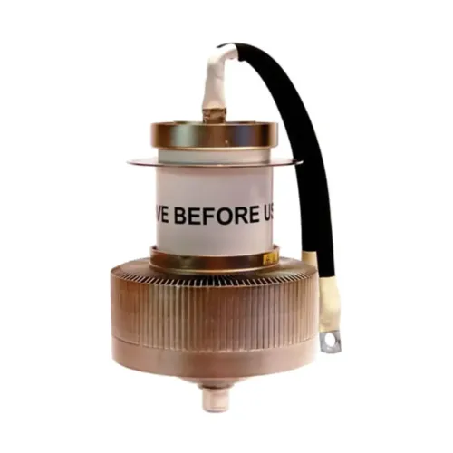
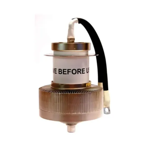
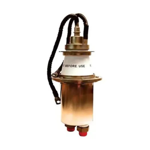
BW1647J2F is a power triode of coaxial ceramic-metal construction. It is intended primarily for industrial RF heating machines. It comes with a removable water jacket. Anode is water cooled.
Electrical Characteristics of BW1647J2F
Filament: Thoriated tungsten
Filament voltage (see note 1): 8.2 V
Filament current: 238 A
Surge filament current (peak) (see note 2): 1200 A max
Filament cold resistance: 4.0 mΩ
Peak usable cathode current: 70 A
Amplification factor (Va = 10 kV, Ia = 5.0 A): 28
Mutual conductance (Va = 10 kV, Ia = 5.0 A): 51 mA/V
Inter-electrode capacitances:
Grid to anode: 47 pF
Grid to filament: 126 pF
Anode to filament: 2.0 pF
Mechanical characteristics of BW1647J2F
Overall dimensions: See outline drawing
Net weight: 12 kg approx, 26.5 pounds approx
Mounting position: Vertical, either way up
Accessories
Water Coupling, supplied: PA709B
Thermal fuse: PA85G
Cathode Connector: PA830
Note: For frequencies above 2 MHz, PA830 should be used in conjunction with a strip connection to provide a low inductance cathode return.
Cooling
| Anode plus grid Dissipation | Minimum inlet temperature (°C) | Minimum water flow (l/min) | Pressure drop (bar) | Outlet temperature (°C) |
|---|---|---|---|---|
| 50 | 20 | 30 | 0.27 | 45 |
| 50 | 50 | 73 | 1.38 | 60 |
| 30 | 20 | 20 | 0.10 | 43 |
| 30 | 50 | 45 | 0.72 | 60 |
| 15 | 20 | 10 | 0.07 | 45 |
| 15 | 50 | 24 | 0.15 | 60 |
The inlet water temperature must never exceed 50 °C. The pressure in the water jacket must not exceed 6 bar. The temperature of the seals and envelope must not exceed 200 °C. Cooling of the seals by low velocity air flow is required.
Radio Frequency Oscillator For Industrial Service (Class C conditions, one tube)
MAXIMUM RATINGS (Absolute values) of BW1647J2F
Frequency: 30 MHz
Anode voltage: 13 kV max
Anode input power: 150 kW max
Anode dissipation: 50 kW
Grid voltage (negative value): 2.0 kV max
Grid Current:
On load: 3.0 A max
Off load: 3.8 A max
Grid dissipation: 1.8 kW max
Grid circuit resistance: 10 kΩ max
Cathode current: 16 A max
Typical Operating Conditions of BW1647J2F
| Parameter | Value 1 | Value 2 | Value 3 | Unit | |||
|---|---|---|---|---|---|---|---|
| Frequency | 30 | 30 | 30 | MHz | |||
| Anode Voltage | 8.0 | 10 | 12 | kV | |||
| Anode current | 8.0 | 10 | 12 | A | |||
| Anode dissipation | 13.6 | 21.1 | 26.3 | kW | |||
| Grid Voltage | -580 | -700 | -860 | V | |||
| Grid resistor | 322 | 318 | 318 | Ω | |||
| Grid current, on load | 1.8 | 2.2 | 2.7 | A | |||
| Grid Current, off load | 2.8 | 3.4 | 3.5 | A | |||
| Grid dissipation | 711 | 1100 | 1600 | W | |||
| Feedback ratio (See note 4) | 13.7 | 13 | 12.8 | % | |||
| Drive Power | 1.7 | 2.6 | 3.9 | kW | |||
| Output Power | 51.9 | 84.6 | 121.9 | kW | |||
| Efficiency | 79.3 | 80 | 82.3 | % | |||
| Oscillator output power (See note 5) | 50.2 | 82 | 118 | kW |
Notes
1. Temporary fluctuations up to + 5% or –10% in filament voltage are permissible.
2. The filament current of BW1647J2F must not exceed 1200 A, even momentarily, at any time.
3. If the BW1647J2F is mounted with the anode uppermost, the water inlet and outlet connections should be reversed.
4. The feedback ratio is defined as Vg (pk)/Va(pk) × 100 where Vg(pk) = peak R.F grid voltage in volts and Va(pk) = peak R.F. anode voltage in volts.
5. Oscillator output power = P out – P drive where Pout = output power of tube to anode circuit and P drive = drive power fed back to grid circuit.