Description
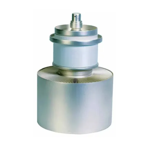
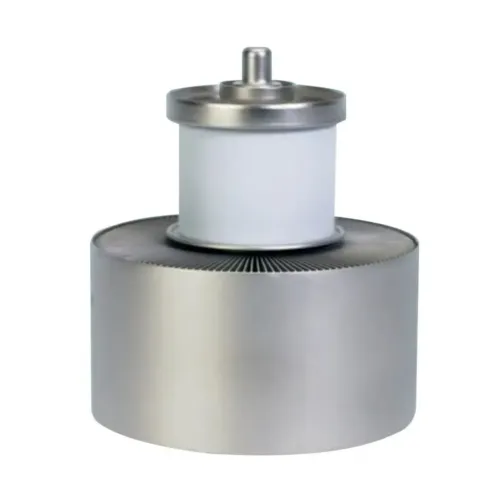
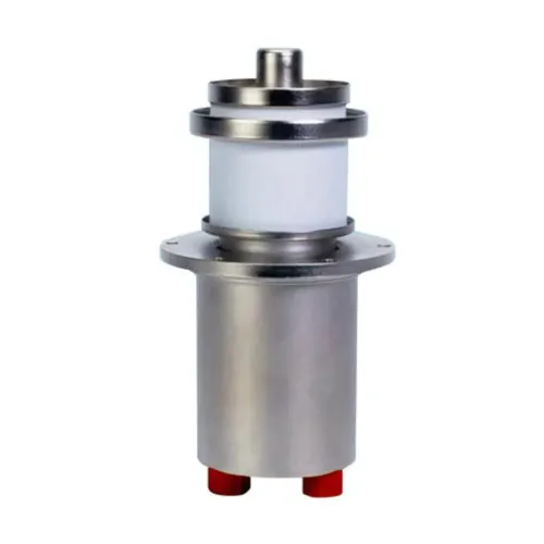
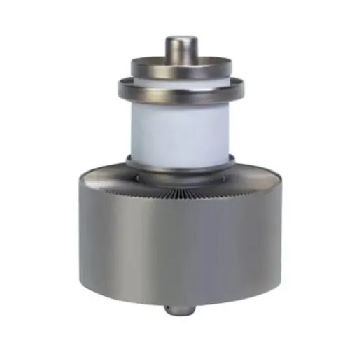
The ITL15-2 is a RF power triode designed specifically for industrial applications. This tube uses a coaxial design and metal-ceramic technology. This triode may be operated in CW or pulse modes. For operation in pulse mode, the parameters depend on each equipment characteristics. Contact us for specific information. The ITL15-2 is a air cooled triode.
Electrical characteristics of ITL15-2
Filament thoriated tungsten
Filament voltage (+5%, -10%) (see note 1) 7.2 V
Filament current 180 A
Surge current (maximum) 500 A
Cold resistance 5 mΩ
Capacitances:
Grid to Anode 25 pF
Grid to Cathode 60 pF
Cathode to Anode (see note 2) 1.4 pF
Amplification factor 25 (approx.)
Transconductance (Va: 4 kV, Ia: 4 A) 60 mA/V (approx.)
Mechanical characteristics of ITL 15-2
Operating position vertical, anode up or down
Weight 9 kg (19 lbs) approx.
Dimensions see outline drawing
Maximum ratings of ITL15-2
Frequency (see note 3) 120 MHz
Anode voltage:
Up to 30 MHz 13 kV
From 30 to 60 MHz 11 kV
From 60 to 90 MHz 9 kV
From 90 to 120 MHz 7 kV
Control grid voltage -1500 V
Anode current 8 A
Control grid current:
Control grid current (at full load) 1.6 A
Control grid current (at no load) 3 A
Peak cathode current, CW 40 A
Anode dissipation:
Inlet air temperature = 25°C 17 kW
Inlet air temperature = 45°C 15 kW
Grid dissipation:
Up to 30 MHz 600 W
From 30 to 60 MHz 520 W
From 60 to 90 MHz 460 W
From 90 to 120 MHz 400 W
Grid resistance (tube non conducting) 10 KΩ
Typical operation of ITL15-2 (see note 4)
Class C RF oscillator for industrial applications
| Frequency | 30 | 30 MHz |
| Anode voltage | 12 | 10 kV |
| Grid bias | -650 | -600 V |
| Grid voltage | 910 | 920 V |
| Anode current | 5 | 6 A |
| Grid current, on load | 0.33 | 0.6 A |
| Anode input power | 60 | 60 kW |
| Anode output power | 45 | 45 kW |
| Anode dissipation | 14.5 | 14.5 kW |
| Grid dissipation | 75 | 170 W |
| Grid resistance | 1970 | 1000 Ω |
| Feedback ratio | 8.4 | 10.2 % |
| Oscillator efficiency | 75 | 75 % |
Note:
1. At frequencies above 50 MHz, the filament voltage of ITL15-2 is reduced so that the ratio of filament voltage to current becomes the same as that without an anode voltage.
2. Measured with a 40 x 40 cm shielding plate attached to the grid plate.
3. Limited conditions above 30 MHz. Please consult Pilani Electron Tubes & Devices.
4. Operation with higher frequencies on request.