Description
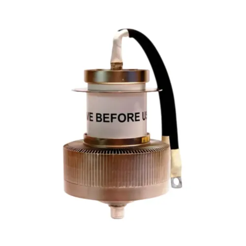
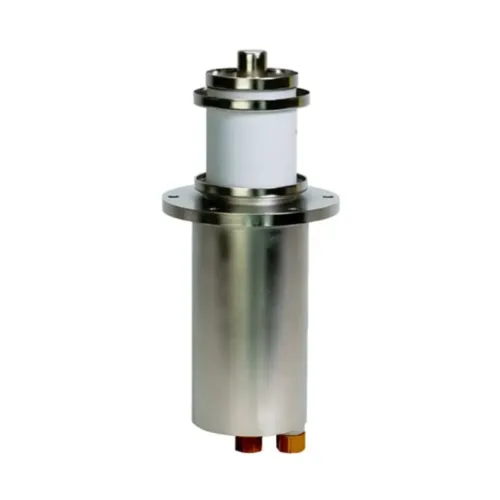
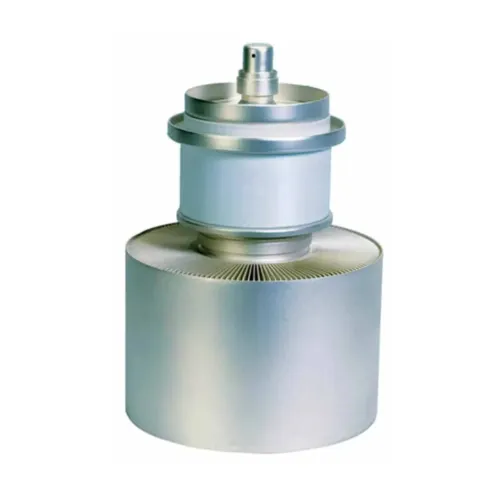
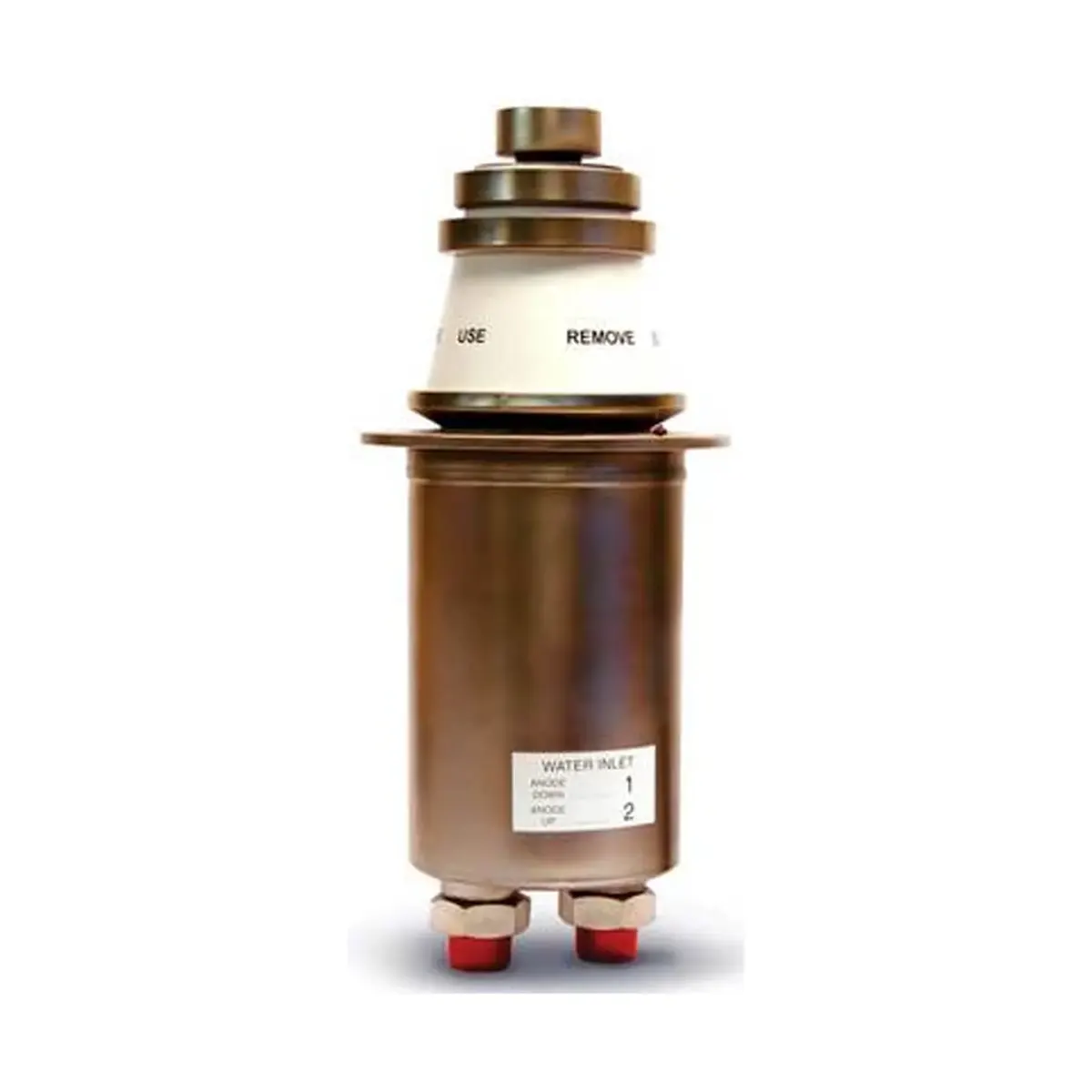
BW1184J2F / YD1202 is a water cooled power triodes of coaxial ceramic-metal construction, intended primarily for industrial RF heating machines. They have removable water jackets. BW1184J2F / YD1202 has integral filament leads.
Electrical Characteristics of BW1184J2F / YD1202
Filament: thoriated tungsten
Filament voltage (see note 1): 12.2 V
Filament current: 255 A
Surge filament current (peak) (see note 2): 1500 A max
Filament cold resistance: 5.3 mΩ
Peak usable cathode current: 106 A
Amplification factor (Va = 10 kV, Ia = 8.0 A): 30
Mutual conductance (Va = 10 kV, Ia = 8.0 A): 150 mA/V
Inter – electrode capacitances:
Grid to anode: 55 pF
Grid to filament: 170 pF
Anode to filament: 2.7 pF
Mechanical Characteristics of BW1184J2F / YD1202
Overall length:
PET1184J2: 446 mm
PET1184J2F: 475 mm
Overall diameter: 190.5 mm (7.500 inches) max
Net weight:
PET1184J2: 11.5 kg approx
PET1184J2F: 12 kg approx
Mounting position (See note 3): Vertical, anode up or down
Accessories
Water coupling (2 supplied with tube): PA709B
Grid connector: PA342
Thermal fuse: PA85G
Radio Frequency Oscillator For Industrial Service
(Class C Conditions, One Tube)
Maximum Ratings (Absolute Valves) of BW1184J2F / YD1202
Frequency: 30 MHz
Anode voltage: 14.4 kV max
Anode input power: 220 kW max
Anode dissipation: 80 kW max
Grid voltage (negative value): 2.0 kV max
Grid current:
On load: 4.0 A max
Off load: 5.5 A max
Grid dissipation: 2.3 kW max
Grid circuit resistance: 10 kΩ max
Cathode current: 22 A max
Cooling
The water cooling requirements of BW1184J2F / YD1202 are given in the table.
| Anode + Grid Dissipation (kW) | Inlet Temp (⁰C) | Min Water Flow (l/min) | Min Water Flow (imp.gal/min) | Inlet Pressure (atm) | Outlet Temp (⁰C) | |
|---|---|---|---|---|---|---|
| 80 | 20 | 40 | 8.8 | 0.35 | 50 | |
| 80 | 50 | 60 | 13.2 | 0.65 | 70 | |
| 60 | 20 | 28 | 6.2 | 0.18 | 52 | |
| 60 | 50 | 42 | 9.2 | 0.32 | 72 | |
| 40 | 20 | 18 | 4.0 | 0.08 | 54 | |
| 40 | 50 | 27 | 6.0 | 0.15 | 73 |
The inlet water temperature of BW1184J2F / YD1202 must never exceed 50 ⁰C.
The temperature of the seals and envelope must not exceed 200 ⁰C. Cooling of the seals by low velocity air flow or water-cooled filament connectors is required.
Typical Operating Conditions
| Parameter | Value 1 | Value 2 |
|---|---|---|
| Frequency | 30 MHz | 30 MHz |
| Anode Voltage | 12 kV | 10 kV |
| Anode Current | 18 A | 16 A |
| Anode Dissipation | 45 kW | 36 kW |
| Grid Voltage | -1080 V | -700 V |
| Grid Resistor | 360 Ω | 200 Ω |
| Grid Current, On Load | 3.0 A | 3.5 A |
| Grid Current, Off Load | 3.8 A | 4.8 A |
| Grid Dissipation | 1.6 kW | 1.5 kW |
| Feedback Ratio (See Note 4) | 15 % | 12 % |
| Drive Power | 4.8 kW | 4.0 kW |
| Output Power | 171 kW | 124 kW |
| Efficiency | 79.5 % | 77.5 % |
| Oscillator Output Power (See Note 5) | 166 kW | 120 kW |
NOTES
1. Temporary fluctuations up to +5% or -10% in filament voltage are permissible.
2. The filament current of BW1184J2F / YD1202 must not exceed 1500 A, even momentarily, at any time.
3. If BW1184J2F / YD1202 is mounted with the anode uppermost, the water inlet and outlet connections should be reversed (see outline).
4. The feedback ratio is defined as Vg(pk) × 100 / Va(pk), where Vg(pk) = peak R.F. grid voltage in volts and Va(pk) = peak R.F. anode voltage in volts.
5. Oscillator output power = Pout – Pdrive, where Pout = output power of tube to anode circuit and Pdrive = drive power fed back to grid circuit.