Description
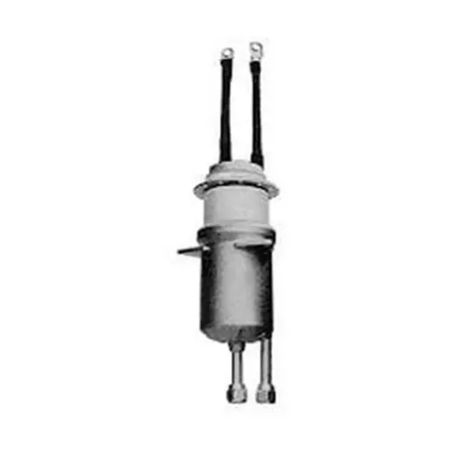
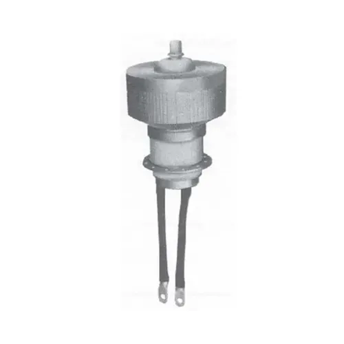
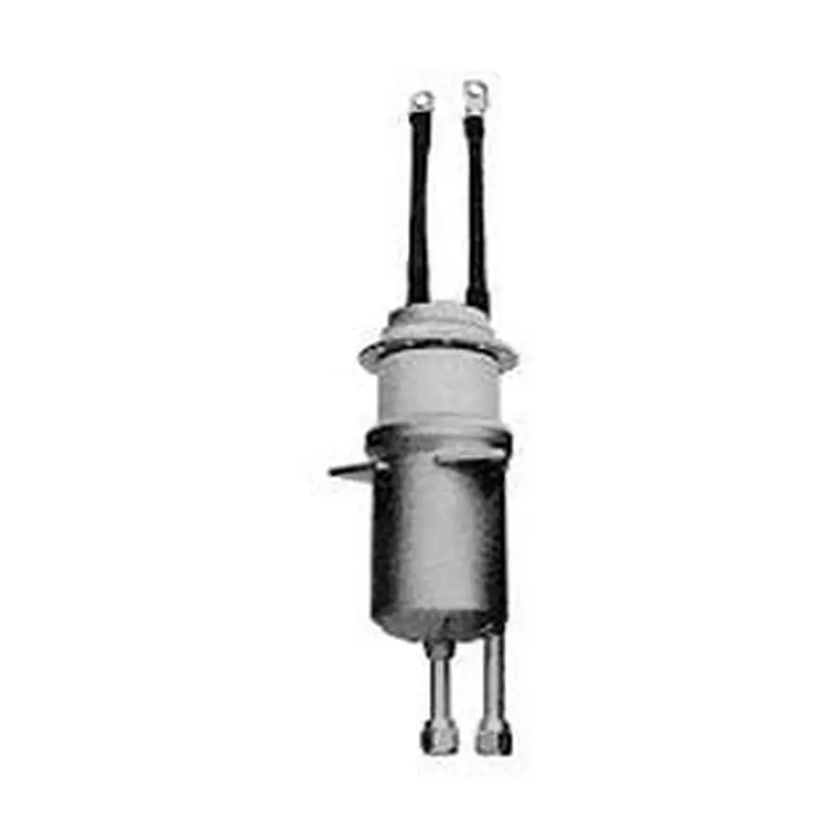
3CW40000H3 is a water-cooled, ceramic-metal power triode with a robust mesh filament, for use in industrial radio-frequency heating.
Electrical Characteristics of 3CW40000H3
| Filament | Thoriated tungsten |
| Filament voltage (see note 1) | 10.0 V |
| Filament current | 160 A |
| Surge Filament current (peak) (see note 2) | 800 A |
| Filament cold resistance | 6.8 mΩ |
| Peak usable cathode current | 50 A |
| Amplification factor | 20 |
| Grid to anode | 46 pF |
| Grid to filament | 77 pF |
| Anode to filament | 2.1 pF |
Mechanical Characteristics of 3CW40000H3
Connections: Filament leads and grid contact flanges
Operating position: Vertical, either way up
Maximum operating temperature: 250 OC
Maximum dimensions: See outline drawing
Net weight: 5 kg (11 pounds) approx
Accessories
Water coupling, supplied with CW40000H3: WPA323A
Thermal fuse available for CW40000H3: PA85E
Cathode connector: PA830
For frequencies above 2MHz, CWPA830 should be used in conjunction with a strip connection to provide a low inductance cathode return.
Cooling
Anode of 3CW40000H3 is cooled by circulating water through the removable anode water jacket. The table lists the minimum water flow requirement for adequate anode cooling at various anode dissipation levels. In all cases, the outlet water temperature must not exceed 70 ⁰C nor should inlet water pressure exceed 60 psi. This table is based upon 20 ⁰C temperature rise.
Additional forced-air cooling of 3CW40000H3 tube base is also required to maintain ceramic-to-metal seal temperature below the 250 ⁰C maximum. Approximately 50 ft3/min of cooling air directed into the base structure will generally satisfy requirements.
Minimum Water Cooling Requirements of 3CW40000H3
| Anode Dissipation (kW) | Water Flow (l/min) | Pressure Drop (psi) |
|---|---|---|
| 30 | 22 | 4.5 |
| 35 | 25 | 5.0 |
| 40 | 29 | 5.5 |
| 45 | 32 | 6.0 |
Radio Frequency Oscillator For Industrial Service
(Class C conditions, one tube)
Maximum Ratings (Absolute Values)
| Frequency | 90 MHz max |
| Anode voltage d.c. | 12 kV max |
| Anode current d.c. (see note 3) | 8.0 A max |
| Anode input power | 80 kW max |
| Anode dissipation | 20 kW max |
| Grid voltage d.c. | -2000 V max |
| Grid current d.c. (see note 4) | 1.5 A max |
| Grid dissipation | 750 W max |
| Cathode current d.c. | 10.0 A max |
Typical Operating Conditions
| Frequency | 30 | 30 MHz |
| Anode voltage d.c. | 7.5 | 10.0 kV |
| Anode current d.c. | 8.0 | 7.9 A |
| Anode dissipation | 9 | 14 kW |
| Grid voltage d.c. | -800 | -900 V |
| Grid resistor | 570 | 1130 Ω |
| Grid current d.c. | 1.4 | 0.8 mA |
| Grid dissipation | 560 | 296 W |
| Drive power | 1670 | 960 W |
| Anode input power | 60 | 79 kW |
| Anode output power | 51 | 65 kW |
| Output power less drive | 49.3 | 64 kW |
NOTES:
- The filament voltage measured at the tube should be 10.0 V ± 5% for satisfactory performance, maximum life is obtained at -5% (9.5 V).
- The filament current of 3CW40000H3 must not exceed 800 A, even momentarily, at any time.
- Maximum anode voltage and current should not be applied simultaneously; this could result in excessive anode dissipation. The anode supply should include current-limiting resistors, and an over-current trip to remove anode voltage quickly in the event of an overload or arc (such load variations and faults are common in industrial services). Spark gaps should be connected between anode and ground, to protect the tube from voltage transients under fault conditions.
- The grid current rating of 1.5 A of d.c. should not be exceeded, except for very short periods during tuning. Normally, reasonable efficiency can be obtained with a grid current not exceeding 0.6 to 1.0 A. the grid circuit should include over-current protection, and d.c. grid current should be monitored continuously during industrial operation with varying loads.