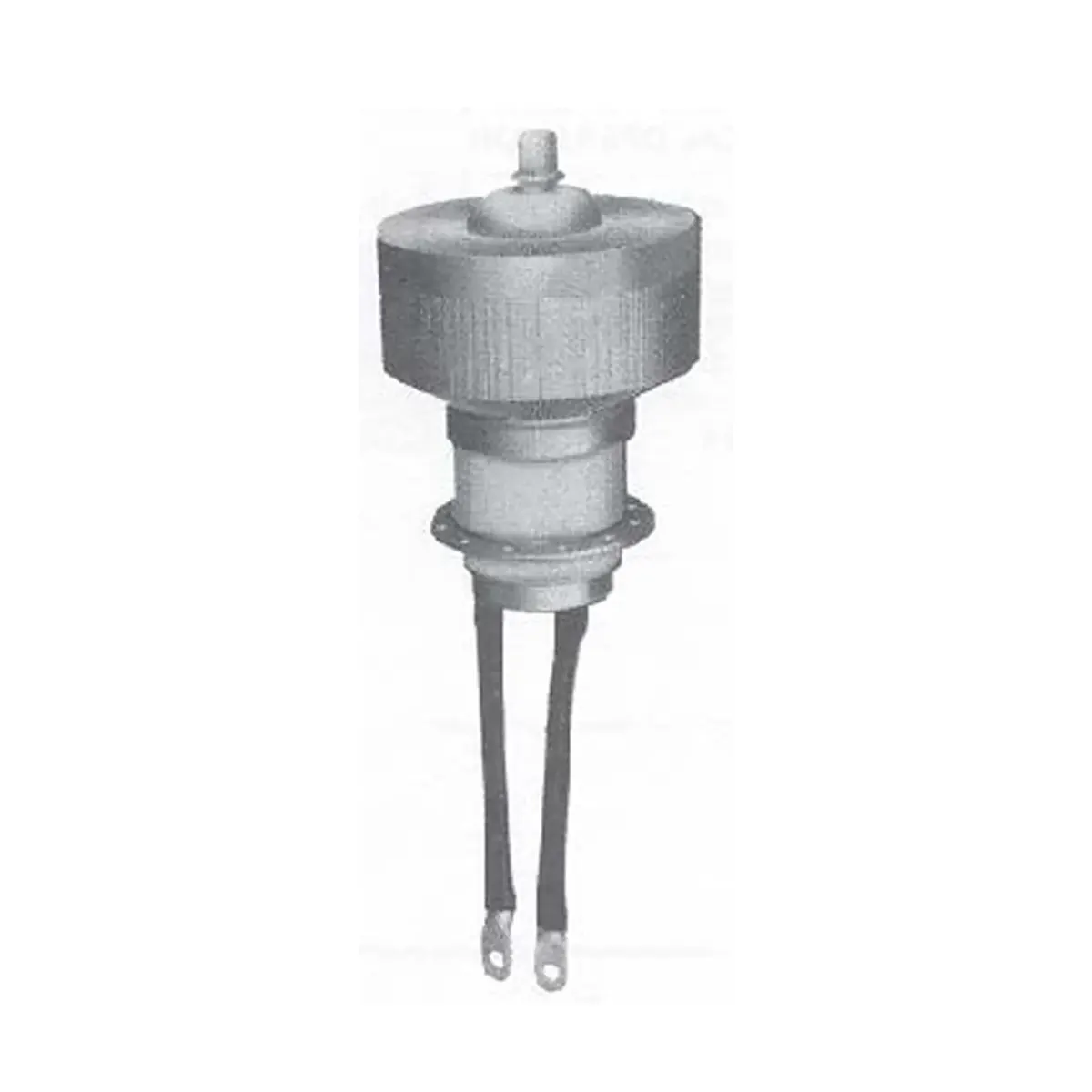
Description
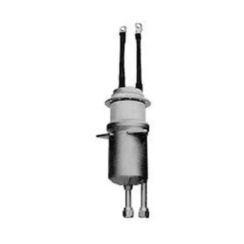
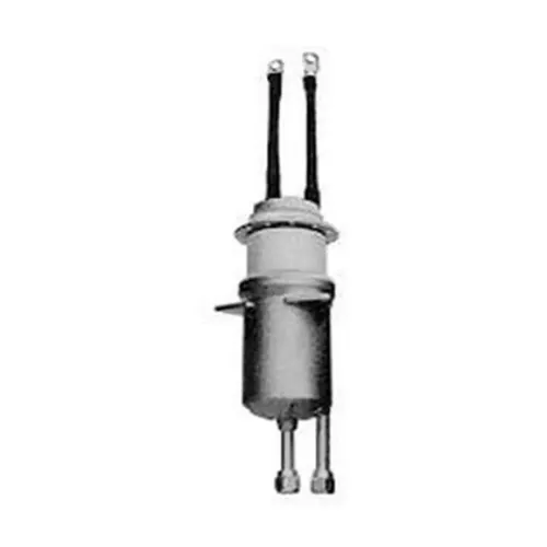
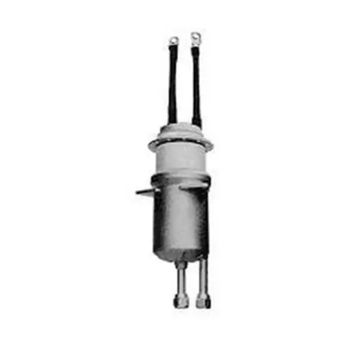
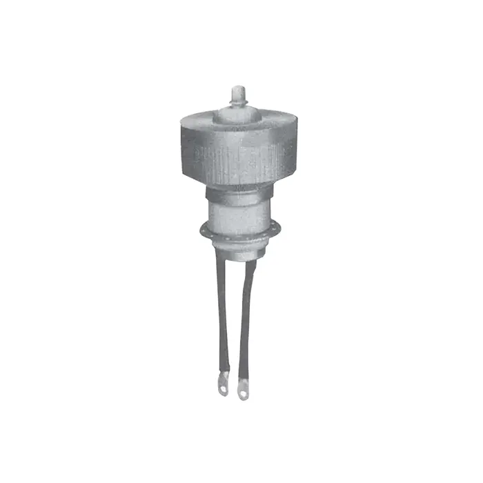
3CX15000H3 is a forced air-cooled, ceramic-metal power triode with a robust mesh filament, for use in industrial radio-frequency heating.
Electrical Characteristics of 3CX15000H3
| Filament | Thoriated tungsten | |
| Filament voltage (see note 1) | 6.3 | V |
| Filament current | 160 | A |
| Surge Filament current (peak) (See note 2) | 800 | A |
| Filament cold resistance | 4.7 | mΩ |
| Peak usable cathode current | 35 | A |
| Amplification factor (Va = 2.3 kV, Ia = 1.0 A) | 20 | |
| Mutual conductance (Va = 2.5 kV, Ia = 1.3 A) | 36 | mA/V |
| Grid to anode capacitance | 39 | pF |
| Grid to filament capacitance | 58 | pF |
| Anode to filament capacitance | 1.9 | pF |
Mechanical Characteristics of 3CX15000H3
Connections: Filament leads and grid contact flange
Operating position: Vertical, either way up
Maximum operating temperature: 250 OC
Maximum dimensions: See outline drawings
Net weight: 6 kg (13 pounds) approx
Accessories of 3CX15000H3
Cathode connector: CWPA830
Note: For frequencies above 2MHz, CWPA830 should be used in conjunction with a strip connection to provide a low inductance cathode return.
Cooling
Sufficient air must be passed through the radiator to keep the temperatures of ceramic to metal seals and of the anode (measured next to the radiator) below the maximum rated value of 250 degree C. The air flows required to maintain seal temperature at 225 degree C in an ambient temperature of 50 degree C and with an operating frequency of less than 30 MHz are shown in the following table.
An additional air flow is required for the filament seals. 16ft3/min directed at the centre contact ring, ½ inch below the outer contact ring, through a 1 ½ inch internal diameter air duct at 45 degree to the axis of the tube, is sufficient for operation up to 30 MHz at 50 degree C ambient and 5000 ft altitude.
Minimum Radiator Air Flow Requirements
| Anode Dissipation (Watts) | Air Flow at Sea Level (ft³/min) | Pressure Drop at Sea Level (inches Water) | Air Flow at 5000 Feet (ft³/min) | Pressure Drop at 5000 Feet (inches Water) |
|---|---|---|---|---|
| 7500 | 361 | 1.63 | 433 | 1.96 |
| 10,000 | 606 | 3.26 | 728 | 3.92 |
| 15,000 | 1260 | 10.0 | 1510 | 12.0 |
The values given allow for maximum filament and grid dissipation in addition to anode dissipation shown.
Radio Frequency Oscillator For Industrial Service
(Class C Conditions, One Tube)
Maximum Ratings (Absolute Values)
| Frequency | 90 | MHz max |
| Anode voltage | 12 | kV max |
| Anode current d.c. (see note 3) | 6.0 | A max |
| Anode input power | 60 | kW max |
| Anode dissipation | 15 | kW max |
| Grid voltage d.c. | 1000 | V max |
| Grid current d.c. (see note 4) | 1.0 | A max |
| Grid dissipation | 500 | W max |
| Cathode current d.c. | 7.0 | A max |
Typical Operating Conditions of 3CX15000H3
| Frequency | 30 | 30 MHz |
| Anode voltage d.c. | 7.0 | 10.0 kV |
| Anode current d.c. | 6.0 | 5.0 A |
| Anode dissipation | 12 | 9 kW |
| Grid voltage d.c. | -600 | -800 V |
| Grid resistor | 910 | 1480 Ω |
| Grid current d.c. | 660 | 540 mA |
| Grid dissipation | 290 | 220 W |
| Drive power | 660 | 650 W |
| Anode input power | 42 | 50 kW |
| Anode output power | 30 | 41 kW |
| Output power less drive | 29.3 | 40.3 kW |
NOTES
1. The filament voltage measured at the tube should be 6.3 V ± 5% for satisfactory performance, maximum life is obtained at -5% (6.0 V).
2. The filament current of 3CX15000H3 must not exceed 800 A, even momentarily, at any time.
3. Maximum anode voltage and current should not be applied simultaneously; this could result in excessive anode dissipation. The anode supply should include current-limiting resistors, and an over-current trip to remove anode voltage quickly in the event of an overload or arc (such load variations and faults are common in industrial service). Spark gaps should be connected between anode and ground, to protect the tube from voltage transients under fault conditions.
4. The grid current rating of 1.0 A d.c. should not be exceeded, except for very short periods during tuning. The grid circuit should include over-current protection, and d.c. grid current should be monitored continuously during industrial operation with varying loads.